DHSBC-STM32MP13
Board Identification
Identifier: DHSBC-STM32MP13 719-300
Yocto MACHINE:
- dh-stm32mp13-dhcor-dhsbc-welma
Documentation:
- https://wiki.dh-electronics.com/index.php?title=DHSBC_STM32MP13
- DOC_DHSBC-STM32MP13-Quick-Start-Guide_R04_2025-04-08.pdf
- USM_DHCOR-STM32MP13_R02_2025-07-07.pdf
Features:
- MPU: STM32MP135f ARM Cortex‑A7 32-bit
- RAM: 512 MB
- Storage: 4GB eMMC, SPI NOR flash 4MB
- EEPROM 4 kB
- 1x USB Host type A, 2.0 high-speed
- 1x USB Device Type-C, 2.0 high-speed
- 2x Ethernet
- WiFi / Bluetooth
Glossary:
- FSBL: First Stage Boot Loader
- FIP: Container made by the Trusted Firmware-A package, that contains optee-os and u-boot
- SSBL: Second Stage Boot Loader
- TF-A: Trusted Firmware-A
Boot Sequence
The Welma boot sequence is as follows:
- ROM Code: loads BL2 (TF-A FSBL) from emmc's boot area partition, and starts it.
- BL2: loads the FIP image from the partition named "fip" (from eMMC user area) and starts:
- OP-TEE (BL32)
- U-Boot (BL33)
- U-Boot: starts the kernel
- The kernel mounts the initial ram file system (initramfs) and starts Init
First installation
-
Connect USB-C DFU X2 connector of the board to your PC
-
Connect FTDI TTL-232R-3V3 X9 connector to your PC, and open a terminal program on this serial console (bitrate 115200)
First Step: Get U-Boot running in RAM
-
Switch boot mode to 123 = ON-ON-ON (USB DFU boot) (warning: depends on the hardware revision!)
-
Power on or reset the board
-
Start U-Boot through DFU
-
Interrupt U-Boot sequence and take control
Second Step: Install Welma on the eMMC using TFTP
-
Have a TFTP server configured and started on your PC
-
Connect the ETH1 X4 port to your PC
-
Install BL2 to emmc's first boot area:
STM32MP> setenv ipaddr 192.168.1.20 STM32MP> setenv serverip 192.168.1.35 STM32MP> tftpboot tf-a-stm32mp135f-dhcor-dhsbc.stm32-stm32mp1 ... Load address: 0xc2000000 Loading: ################################################## 78.5 KiB 1.3 MiB/s ... STM32MP> setexpr nblocks $filesize + 0x1ff STM32MP> setexpr nblocks $nblocks / 0x200 STM32MP> mmc dev 0 1 STM32MP> mmc write $loadaddr 0 $nblocks MMC write: dev # 0, block # 0, count 157 ... 157 blocks written: OK -
Set the emmc to boot from emmc's first boot area:
-
Install FIP, kernel and filesystems to emmc's user area:
STM32MP> setenv ipaddr 169.254.142.1; setenv serverip 169.254.142.224;
STM32MP> tftpboot demo-image-headless-dev-dh-stm32mp13-dhcor-dhsbc-welma.wic.gz
STM32MP> gzwrite mmc 0 $loadaddr $filesize
Regular Boot
The regular boot on a SD card is done as follows:
-
Switch boot mode to 1-2-3 = OFF-ON-OFF (warning: depends on the hardware revision!)
-
Reset or start the board
Appendix
Connecting the board
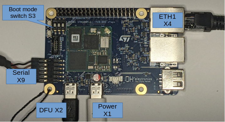
- X1: USB Type-C Power supply
- X2: USB Type-C for DFU and UMS data connection
- X4: Ethernet ETH1
- X9: Serial console, baud rate 115200. Use FTDI cable TTL-232R-3V3.
- S3: Boot switch mode, see next section
Boot mode switch S3
Warning
The boot mode switch depends on the hardware revision. Please refers to your board's documentation.
| 1-2-3 | Boot mode |
|---|---|
| ON-OFF-OFF | SPI NOR flash |
| OFF-ON-OFF | eMMC |
| ON-ON-ON | USB DFU |
Boot from SPI NOR flash
If, instead of booting from emmc, you want the board to boot from the SPI NOR flash, this section explains how to install and start.
-
Prerequisites:
- Have a running U-Boot on the board (see First Installation)
-
(optional) Erase the SPI NOR flash (takes about 1 min)
-
Install bootloader to SPI NOR flash:
U-Boot side:
STM32MP> sf probe
STM32MP> env set dfu_alt_info "mtd nor0=fsbl1 raw 0x0 0x40000;fip raw 0x80000 0x160000"
STM32MP> dfu 0 mtd
Host PC side:
$ dfu-util -a 0 -D tf-a-stm32mp135f-dhcor-dhsbc.stm32-stm32mp1
$ dfu-util -a 1 -D fip-stm32mp1-dev.bin
-
Switch boot mode to 1-2-3 = ON-OFF-OFF (depends on the hardware revision!)
-
Power cycle the board
Hardware watchdog
The hardware watchdog is:
- Started by U-Boot (timeout 32 s)
- Serviced by the Linux kernel (as long as no userspace process opens /dev/watchdog0 and takes over)
- Then serviced by systemd
Fusing ethernet MAC addresses in OTP
When boards are not provisioned with ethernet MAC addresses, U-Boot assigns random values at each boot, and this is generally not what we need.
This section explains how to fix these MAC addresses by writing fixed values in OTP registers.
- Read MAC addresses registers:
Warning
The following commands are writing to One-Time Programmable (OTP) eFuses. Programming fuses is an irreversible operation! Doing this with wrong values, or several times may brick your system. Use these commands only if you are sure of what you are doing!
- Program MAC addresses:
-
Lock MAC addresses:
-
Check:
Ref: https://wiki.st.com/stm32mpu/wiki/How_to_update_OTP_with_U-BootSTM32MP> fuse sense 0 0x39 3 Sensing bank 0: Word 0x00000039: 3d62b4e6 265a67d5 6984c430 STM32MP> fuse sense 0 0x10000039 3 Sensing bank 0: Word 0x10000039: 40000000 40000000 40000000 STM32MP> reset ... STM32MP> printenv ... eth1addr=5a:26:30:c4:84:69 ethaddr=e6:b4:62:3d:d5:67 ...