STM32MP257F-DK
1. Board Identification
Identifier: STM32MP257F-DK
Yocto MACHINE:
- stm32mp25-disco-welma
Documentation:
Features:
- MPU: STM32MP257f dual ARM Cortex‑A35 64-bit + ARM Cortex‑M33 32-bit
- 3D GPU up to 900 MHz
- NPU up to 900 MHz
- RAM: up to 4 GB DDR
- Two Octo-SPI memory interfaces
- 1-Gbit/s Ethernet (RGMII)
- x2 USB 2.0 high speed
- Wi-Fi 802.11b/g/n
- BLE v4.1
- Dual-lane MIPI CSI-2 camera module expansion connector
- HDMI
- LVDS
2. Boot Sequence
The boot sequence from an SD card, as follows:
- The ROM Code loads TF-A (BL2, FSBL) from the first GPT partition (raw) into SRAM (System RAM inside MPU), and starts it.
- TF-A:
- Initializes DRAM (used in the following steps)
- Loads the FIP container (SSBL) from the partition named "fip"
- Launches OP-TEE (BL32)
- OP-TEE launches U-Boot (BL33) (in DRAM)
- U-Boot starts the kernel
- The kernel mounts the initial ram file system (initramfs) and starts Init
Reference: Trusted Firmware-A
Glossary:
- FSBL: First Stage Boot Loader
- SSBL: Second Stage Boot Loader
- DRAM: Dynamic RAM, external to the MPU
- TF-A: Trusted Firmware-A
3. First installation
There are two options for installing software on the board:
- Flashing the SD card on a PC, as explained in the quick start.
- Using DFU mode and TFTP, as explained in this section.
First Step: Get U-Boot running in RAM
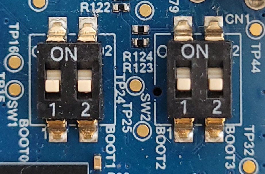
- Set the boot mode pins, to make the ROM Code start in mode DFU over USB:
- BOOT0 OFF
- BOOT1 OFF
- BOOT2 OFF
- BOOT3 OFF
'OFF' is considered when switch is pushed OPEN position and is 'ON' otherwise (see picture below)
- Connect your cables between the board and the PC:
- Power and Serial port (USB PWR STLINK)
- USB OTG (USB DRD)
- Have the board load and execute TF-A / OP-TEE / U-Boot in RAM through the dfu-util tools:
  $ DEPLOY_DIR_IMAGE=tmp/deploy/images/stm32mp25-disco-welma
  # Download phase 0x1 by ROM code is the FSBL (TF-A BL2)
  $ dfu-util -a 0 -D $DEPLOY_DIR_IMAGE/arm-trusted-firmware/tf-a-stm32mp257f-dk-optee-programmer-usb_signed.stm32
  # DFU detach to request an FSBL start
  $ dfu-util -a 0 -e
  # Download phase 0x2 by FSBL is the FIP file including the DDR settings
  $ dfu-util -a 0 -D $DEPLOY_DIR_IMAGE/fip/fip-stm32mp257f-dk-ddr-optee-programmer-usb_signed.bin
  # DFU detach to request handle DDR initalization - not required for STM32MP1 series
  $ dfu-util -a 0 -e
  # Download phase 0x3 by FSBL is the FIP file including the SSBL image (U-Boot)
  $ dfu-util -a 1 -D $DEPLOY_DIR_IMAGE/fip/fip-stm32mp257f-dk-optee-programmer-usb_signed.bin
  # DFU detach to request an SSBL start
  $ dfu-util -a 0 -e
Note
The artifact file names may change depending on the version of Yocto
you have chosen. Please check your DEPLOYDIR to use the correct file names.
Second Step: Install Welma on the eMMC using TFTP
- Connect your cables between the board and the PC:
- Serial port ST-LINK
-
Ethernet
-
Take control of U-Boot, download the eMMC image via TFTP and write it to its destination:
-
Since the ROM code in the STM32MP25 only supports booting from eMMC hardware partitions, TF-A binary must be installed in eMMC boot partitions 1 and 2:
STM32MP> tftp welma/tf-a-stm32mp257f-dk-optee-emmc_signed.stm32 STM32MP> setexpr blkcnt $filesize + 0x1ff STM32MP> setexpr blkcnt $filesize / 0x200 # blkcnt should me a multiple of 512 (0x200) STM32MP> mmc dev 1 # select the eMMC STM32MP> mmc partconf 1 1 1 1 # Select boot1 to be accessed for read/write STM32MP> mmc write $loadaddr 0 $blkcnt # write TF-A on boot1 STM32MP> mmc partconf 1 1 2 2 # Select boot2 to be accessed for read/write STM32MP> mmc write $loadaddr 0 $blkcnt # write TF-A on boot2 STM32MP> mmc partconf 1 1 1 0 # Set boot1 as next boot partition (or 1 1 2 0 for boot2) -
Switch the boot mode pins, to make the ROM Code boot from the eMMC:
- BOOT0 OFF
- BOOT1 ON
- BOOT2 OFF
- BOOT3 OFF
-
Reboot the board
Regular Boot
The regular boot is done from eMMC, as follows:
- Set the boot switch to boot from eMMC
- Start the board.
Appendix
Install Welma using UMS
- Connect the serial port and OTG
- Execute the following command in U-Boot command line to export HW
boot1partition: At this level, the eMMC of the board appears as a connected device to the host machine, named /dev/sdX. It acts as a simple external hard drive plugged on the host USB port. - Copy TF-A to the eMMC card, say /dev/sdc
Warning
Be sure to use the correct device path in order not to accidentally overwrite another disk
- Export HW
boot2partition: - Copy TF-A to the eMMC card
- Export user data partitions
- Copy the generated WIC image to the eMMC card
- Set HW
boot1as boot partition -
Switch the boot mode pins, to make the ROM Code boot from the eMMC:
- BOOT0 OFF
- BOOT1 ON
- BOOT2 OFF
- BOOT3 OFF
-
Reset the board
Boot from SDCard
To boot from an SD card, TF-A and U-Boot must be configured as such. To do this:
-
Set the
BOOTDEVICE_SELECTconfiguration variable inconf/local.conftosdcard: -
Rebuild the image
-
Plug the SDCard to the host machine and copy the generated WIC image into it, say /dev/sdc
Warning
Be sure to use the correct device path in order not to accidentally overwrite another disk
- Switch the boot mode pins, to make the ROM Code boot from the eMMC:
- BOOT0 ON
- BOOT1 OFF
- BOOT2 OFF
- BOOT3 OFF
- Power on the board
Hardware Watchdog
STM32MP257F-DK uses the ARM SMC hardware Watchdog.
- Started by U-Boot (timeout 32 s)
- Serviced by the Linux kernel (as long as no userspace process opens /dev/watchdog0 and takes over)
Boot related switches
The STM32MP257x-DK Evaluation boards can boot from different Flash devices (microSD, eMMC, S-NOR...):
| Boot mode | Boot 3 | Boot 2 | Boot 1 | Boot 0 |
|---|---|---|---|---|
| USB | 0 | 0 | 0 | 0 |
| microSD | 0 | 0 | 0 | 1 |
| eMMC | 0 | 0 | 1 | 0 |
| Development boot | 0 | 0 | 1 | 1 |
The values of the BOOT pins are sampled by boot ROM after a reset.